This is the pinmap of your Smart Inventor Board, this will come in handy when you start learning to program your board. Use the tabs below to learn more about all the components that are installed inside of your Smart Inventor Board.

[su_accordion class=””]
[su_spoiler title=”PIN MODE: INPUT” open=”no” style=”default” icon=”plus” anchor=”” class=””]These are the digital IR sensors located at the bottom of your smart inventor board. The Smart Inventor Board has 7 IR sensors along the bottom side of the board. Learn to program them here.[/su_spoiler]
[su_spoiler title=”PINMODE: OUTPUT” open=”no” style=”default” icon=”plus” anchor=”” class=””]These are the 8 LEDs located along the topside of the Smart Inventor Board. Learn to program them here.[/su_spoiler]
[su_spoiler title=”BUZZER: USE TONE” open=”no” style=”default” icon=”plus” anchor=”” class=””]This is the piezoelectric buzzer installed on pin 7 of your Smart Inventor Board. This will vibrate and make noises! Learn more about how to program them here.[/su_spoiler]
[su_spoiler title=”DC MOTOR CONTROL” open=”no” style=”default” icon=”plus” anchor=”” class=””]These are your DC Motor Pins. Please ensure that when you plug these in that they are placed horizontal and not vertical.
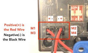
Learn more about how to program these here.[/su_spoiler]
[su_spoiler title=”LEFT IR SENSOR, CENTER IR SENSOR, RIGHT IR SENSOR” open=”no” style=”default” icon=”plus” anchor=”” class=””]These are the analog IR Sensors for the Smart Inventor Board. When using the default program on the board, you can use them to navigate and select which program you would like to run. Ambient lighting may also affect these sensors so try not to use the board next to direct or ambient sunlight. Learn more about these sensors here.[/su_spoiler]
[/su_accordion]
[su_accordion class=””]
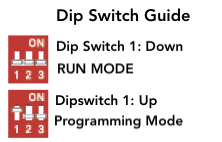
[su_spoiler title=”DIP SWITCH” open=”no” style=”default” icon=”plus” anchor=”” class=””]The Smart Inventor Board comes with 3 Dip Switches. Depending on the positioning the switches will allow you to either enter programming mode, (so you can use Arduino), or execute the program installed in the Smart Inventor board. Our default program is already pre installed in every Smart Inventor Board, If you ever need to reset your board please use the following link to do so, click here.
 [/su_spoiler]
[su_spoiler title=”VR (VARIABLE RESISTOR)” open=”no” style=”default” icon=”plus” anchor=”” class=””]This is the variable resistor used to control the sensitivity of the bottom IR Sensors. Learn more about them here.[/su_spoiler]
[su_spoiler title=”IR RECEIVER” open=”no” style=”default” icon=”plus” anchor=”” class=””]This is the IR receiver. The Smart Inventor Board library makes it really easy to program this so that you can use the remote control to program your robot! Make sure that you point your RF remote at this when you are pressing buttons on your robot gets the commands you send from the remote. Learn more about the remote here.[/su_spoiler]
[su_spoiler title=”PORT D” open=”no” style=”default” icon=”plus” anchor=”” class=””]These are the external digital pins on your board. Although not included, you can purchase any digital components (such as LEDs, Servos, etc.) to build more projects! The board comes with 5 pins (27-31) that you can use to expand your projects using any Arduino compatible components.[/su_spoiler]
[su_spoiler title=”PORT A” open=”no” style=”default” icon=”plus” anchor=”” class=””]These are the external analog pins on your board. Although not included, you can purchase any arduino compatible sensors to build more projects! The board comes with 5 pins (22-26) that you can use to enhance your designs.[/su_spoiler]
[/su_accordion]